Receivers (HCEs)#
A heat collection element (HCE) is a metal pipe contained in a vacuum within glass tube that runs through the focal line of the trough-shaped parabolic collector. Seals and bellows ensure that a vacuum is maintained in each tube. Anti-reflective coatings on the glass tube maximize the amount of solar radiation that enters the tube. Solar-selective radiation absorbing coatings on the metal tube maximize the transfer of energy from the solar radiation to the pipe.
The Receivers (HCEs) variables describe the properties of up to four HCE types that can make up the solar field. This makes it possible to model a solar field with HCEs in different states. Each set of properties applies to one of the HCE types. The Fraction of Field variable determines what portion of the solar field is made up of a given HCE type.
- Current HCE inputs
The name of the receiver and its condition. Vacuum refers to an HCE in good condition, lost vacuum, broken glass, and hydrogen refer to different problem conditions. You can define up to four HCE (receiver) conditions.
- Fraction of Field
Fraction of solar field using this HCE type and condition. Used to calculate HCE field error factor and HCE heat loss.
- Bellows Shadowing
The portion of the HCE tube that does not absorb solar thermal radiation. Used to calculate HCE field error factor.
- Envelope Transmissivity
Used to calculate HCE field error factor.
- Absorber Absorption
Accounts for inefficiencies in the HCE black coating. Used to calculate HCE field error factor.
- Unaccounted
Allows for adjustment of the HCE performance to explore effect of changes in performance of the HCE without changing the values of other correction factors. A typical value is 1. Used to calculate HCE field error factor.
- Optical Efficiency (HCE)
The design optical efficiency of each of the four receiver type and condition options. SAM uses the values to calculate the design weighted optical efficiency.
Optical Efficiency = SCA Field Error × Dust on Envelope × Bellows Shadowing × Envelope Transmissivity × Absorber Absorption × Unaccounted
SCA Field Error = Tracking Error and Twist × Geometric Accuracy × Mirror Reflectivity × Mirror Cleanliness Factor × Concentrator Factor
- Optical Efficiency (Weighted)
The design weighted optical efficiency, representing the average optical efficiency of all receivers in the field. SAM uses the value to calculate the solar field area. Note that SAM also calculates a separate HCE optical efficiency value for each hour during simulation that counts for the loss factors on the SCA / HCE page that also accounts for the incident angle modifier factor, which depends on the time of day and collector orientation.
Optical Efficiency Weighted = Optical Efficiency 1 × Percent of Solar Field 1 + Optical Efficiency 2 × Percent of Solar Field 2 + Optical Efficiency 3 × Percent of Solar Field 3 + Optical Efficiency 4 × Percent of Solar Field 4
- Heat Loss Coefficient A0…A6
Used to calculate the HCE heat loss. The default values are based on NLR modeling and test results. (See Forristall R, 2003. Heat Transfer Analysis and Modeling of a Parabolic Trough Solar Receiver Implemented in Engineering Equation Solver. National Renewable Energy Laboratory NREL/TP-550-34169, https://www.nlr.gov/docs/fy04osti/34169.pdf; Burkholder F et al, 2009, Heat Loss Testing of Schott’s 2008 PTR70 Parabolic Trough Receiver. National Renewable Energy Laboratory NREL/TP-550-45633, https://www.nlr.gov/docs/fy09osti/45633.pdf )
- Heat Loss Factor
The design heat loss factor that applies to the active HCE type and condition. Used to calculate design HCE heat loss that is part of the solar field area equation. The heat loss factor scales the heat loss equation and can be used to fine tune the results when measured heat loss data are available. The default value of 1.0 is valid for the current version of SAM using the default heat loss coefficients.
- Min windspeed (m/s)
Used to calculate the HCE heat loss for hours when the wind speed from the weather file is lower than the minimum wind speed.
The following heat loss values are provided for reference. SAM calculates the HCE heat loss for each hour during simulation based on the loss factor coefficients on the SCA / HCE page and other values from the weather data.
- HCE Heat Losses (W/m)
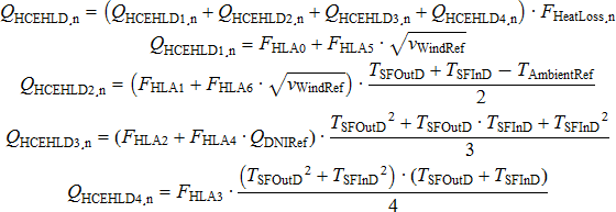
Where,
QHCEHLD,n (W/m) |
HCE heat losses for HCE type n expressed in thermal Watts per meter |
FHeatLoss,n |
Heat Loss Factor for HCE type n |
FA0 … FA6 |
A0 Heat Loss Coefficient through A6 Heat Loss Coefficient |
TSFin (°C) |
Solar Field Inlet Temperature from the Solar Field page |
TSFout (°C) |
Solar Field Outlet Temperature from the Solar Field page |
TAmb (°C) |
Reference ambient temperature from the Solar Field page |
QDNIRef |
Reference direct normal radiation from the Solar Field page |
nWind (m/s) |
Reference wind velocity from the Solar Field page |
Thermal Losses (Weighted W/m) Thermal Losses Weighted W/m = HCE Heat Losses 1 × Percent of Solar Field 1 + HCE Heat Losses 2 × Percent of Solar Field 2 + HCE Heat Losses 3 × Percent of Solar Field 3 + HCE Heat Losses 4 × Percent of Solar Field 4
- Thermal Losses (Weighted W/m2)
Thermal Losses Weighted W/m2 = Thermal Losses Weighted W/m ÷ SCA Aperture
About the HCE Parameters#
The HCE library includes four HCE types, and for each HCE type, five HCE conditions. See Working with Libraries for information about managing libraries.
For each HCE type and condition, you can assign a Percent of Field value. For example, in the figure below, the receiver type is Schott PTR70, and 98.5% percent of the HCEs are in normal condition, 1.0% have lost vacuum, 0.5% have glass damage, and 0% have allowed hydrogen to enter the tube.
When you select a name from the Receiver Type and Condition list, SAM populates the optical and heat loss parameters using values stored in the library. When you change one or more of these values, SAM creates a copy of the parameter set and adds it to the library under the name “CUSTOM CUSTOM.”
The four HCE types are described in the table below.
Table . Default HCE types.
HCE Type |
Description |
|---|---|
Luz Cermet |
Original HCE design. Low reliability of seals. |
Schott PTR70 Vacuum |
Newer design with improved reliability. Two versions are available. |
Solel UVAC2 |
Newer design with improved reliability. |
Solel UVAC3 |
The newest HCE available as of May 2008. |
The performance of the HCE is highly dependent on the quality of the vacuum in the glass tube. SAM models the HCE under the five conditions described in the following table.
Table . HCE conditions.
HCE Condition |
Description |
|---|---|
Broken glass |
Glass tube is damaged, increasing heat transfer between tube and atmosphere. |
Fluorescent |
Selective coating on metal tube is compromised, reducing absorption of solar radiation |
Hydrogen |
Hydrogen from hydrocarbon-based heat transfer fluid (e.g., mineral oil) has permeated through metal tube into the vacuum, increasing heat transfer between metal tube and glass. |
Lost vacuum |
Glass-to-metal seal is compromised |
Vacuum |
HCE is not damaged and is operating as designed. |