Thermal Storage#
Thermal Energy Storage (TES)#
- Full Load Hours of TES
The thermal storage capacity expressed in number of hours of thermal energy delivered at the power block’s design thermal input level. The physical capacity is the number of hours of storage multiplied by the power block design thermal input. Used to calculate the TES maximum storage capacity.
- Max thermal capacity (MWh)
The maximum thermal energy storage capacity of the TES, assuming that thermal storage can be fully discharged (see Thermal Storage Dispatch Control).
- Charging energy derate
SAM applies the derate factor to the turbine efficiency for trough systems with storage to account for the lower steam temperature that results from imperfect heat exchange in the storage system.
- Discharging energy derate
Efficiency adjustment factor. Used to calculate maximum TES discharge rate.
- Initial charge fraction
The initial charge fraction specifies the fractional state of charge in thermal storage at the initial time step of the simulation. A fraction of 0 indicates no thermal energy stored, while a fraction of 1 indicates full state of charge.
- Thermal loss multiplier (kWt/MW-hr-cap)
The thermal loss multiplier specifies the baseline rate of heat loss in kWt from storage per MW-hr of thermal energy capacity for the storage system. For example, a value of 0.35 kWt/MW-hr-cap on a plant with 1,000 MW-hr of storage capacity corresponds to a baseline heat loss of 350 kWt. The heat loss may be altered according to the state of charge and ambient temperature, as described below.
- Charge based loss adj
Coefficients for evaluating a polynomial equation that adjust thermal losses from the thermal storage system based on charge level. The polynomial is formulated as follows:

where Xcharge is the fractional charge level of the thermal storage system. The fractional charge is evaluated at the average charge level over the time step.
- Temp based loss adj
Coefficients for evaluating a polynomial equation that adjust thermal losses from the thermal storage system based on ambient temperature. The polynomial is formulated as follows:

where Tsf,des is the design-point solar field ambient temperature defined on the Solar Field page.
The total thermal loss from thermal storage is calculated as the product of the Thermal loss multiplier Fhl,ref, the capacity of the thermal storage system ETES,cap, and the sum of the evaluated loss adjustment polynomials.

Charge based exergy adj The charge-based exergy adjustment factor allows you to modulate the exergetic state of energy that is discharged from thermal storage as a function of the state of charge in thermal storage. Either a single value or a table of values may be specified. The exergy penalty may be applied using either a “direct storage” or “indirect storage” configuration. The exergy adjustment affects the power cycle conversion efficiency in the following manner:
Where ηcycle,desis the design-point cycle conversion efficiency, η’cycleis the calculated cycle efficiency before exergy adjustment is applied, and Fexergyis the exergetic correction factor. This factor is determined as follows:
If a single value is specified, that value is always used
If a table is specified, the exergetic penalty is determined by interpolating the state of charge and returning the corresponding exergetic penalty.
If the “direct storage” option is enabled, all energy sent to the power cycle is adjusted in this way. If the “indirect storage” option is enabled, energy coming from the solar field is first sent to the power cycle (as available) and incurs no penalty, and only supplemental energy coming from thermal storage is penalized.
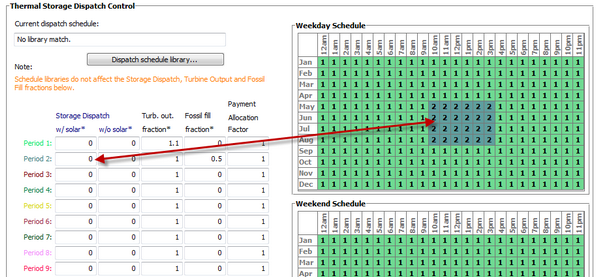
Thermal Storage Dispatch Control#
The storage dispatch control variables each have six values, one for each of six possible dispatch periods. They determine how SAM calculates the energy flows between the solar field, thermal energy storage system, and power block. The fossil-fill fraction is used to calculate the energy from a backup boiler.
- Storage Dispatch Fraction with Solar
The fraction of the TES maximum storage capacity indicating the minimum level of charge that the storage system can discharge to while the solar field is producing power. A value of zero will always dispatch the TES in any hour assigned to the given dispatch period; a value of one will never dispatch the TES. Used to calculate the storage dispatch levels.
- Storage Dispatch Fraction without Solar
The fraction of the TES maximum storage capacity indicating the minimum level of charge that the storage system can discharge to while no solar resource is available. A value of zero will always dispatch the TES in any hour assigned to the given dispatch period; a value of one will never dispatch the TES. Used to calculate the storage dispatch levels.
- Turbine Output Fraction
The fraction of design-point thermal load to the power block before part-load and temperature efficiency corrections. These values allow the user to dispatch the power cycle at a desired level according to the time-of-dispatch period.
- Fossil Fill Fraction
A fraction of the power block design turbine gross output from the Power Block page that can be met by the backup boiler. Used by the power block module to calculate the energy from the backup boiler.
If you specify a fossil fill fraction other than zero for one or more periods and want to account for fuel costs in the financial model, you should assign a fossil fuel cost on the Operating costs page.
Storage and Fossil Dispatch Controls#
The thermal storage dispatch controls determine the timing of releases of energy from the thermal energy storage and fossil backup systems to the power block. When the system includes thermal energy storage or fossil backup, SAM can use a different dispatch strategy for up to six different dispatch periods.
Storage Dispatch#
SAM decides whether or not to operate the power block in each hour of the simulation based on how much energy is stored in the TES, how much energy is provided by the solar field, and the values of the thermal storage dispatch controls parameters. You can define when the power block operates for each of the six dispatch periods. For each hour in the simulation, if the power block is not already operating, SAM looks at the amount of energy that is in thermal energy storage at the beginning of the hour and decides whether it should operate the power block. For each period, there are two targets for starting the power block: one for periods of sunshine (w/solar), and one for period of no sunshine (w/o solar).
The turbine output fraction for each dispatch period determines at what load level the power block runs using energy from storage during that period. The load level is a function of the turbine output fraction, design turbine thermal input, and the five turbine part load electric to thermal factors on the Power Block page.
For each dispatch period during periods of sunshine, thermal storage is dispatched to meet the power block load level for that period only when the thermal power from the solar field is insufficient and available storage is equal to or greater than the product of the storage dispatch fraction (with solar) and maximum energy in storage. Similarly, during periods of no sunshine when no thermal power is produced by the solar field, the power block will not run except when the energy available in storage is equal to or greater than the product of storage dispatch fraction (without solar) and maximum energy in storage.
By setting the thermal storage dispatch controls parameters, you can simulate the effect of a clear day when the operator may need to start the plant earlier in the day to make sure that the storage is not filled to capacity and solar energy is dumped, or of a cloudy day when the operator may want to store energy for later use in a higher value period.
Fossil Dispatch#
When the fossil fill fraction is greater than zero for any dispatch period, the system is considered to include fossil backup. The fossil fill fraction defines the solar output level at which the backup system runs during each hour of a specific dispatch period. For example, a fossil fill fraction of 1.0 would require that the fossil backup operate to fill in every hour during a specified period to 100% of design output. In that case, during periods when solar is providing 100% output, no fossil energy would be used. When solar is providing less than 100% output, the fossil backup operates to fill in the remaining energy so that the system achieves 100% output. For a fossil fill fraction of 0.5, the system would use energy from the fossil backup only when solar output drops below 50%.
The boiler LHV efficiency value on the Power Block page determines the quantity of fuel used by the fossil backup system. A value of 0.9 is reasonable for a natural gas-fired backup boiler. SAM includes the cost of fuel for the backup system in the levelized cost of energy (LCOE) and other metrics reported in the results, and reports the energy equivalent of the hourly fuel consumption in the time series simulation results. The cost of fuel for the backup system is defined on the Operating costs page.
Defining Dispatch Schedules#
The storage dispatch schedules determine when each of the six periods apply during weekdays and weekends throughout the year.
If your analysis includes PPA price multipliers and you want to use the same schedule for the multipliers and for the power cycle dispatch control, click Copy schedule from TOD Factors page to apply the TOD Factors schedule matrices to the dispatch schedule matrices.
To specify a weekday or weekend schedule:
Assign values as appropriate to the Storage Dispatch, Turbine Output Fraction, and Fossil Fill Fraction for each of the up to nine periods.
Use your mouse to draw a rectangle in the matrix for the first block of time that applies to period 2.

Type the number 2.
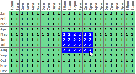
SAM shades displays the period number in the squares that make up the rectangle, and shades the rectangle to match the color of the period.
Repeat Steps 2-4 for each of the remaining periods that apply to the schedule.