Solar Field#
System Design Point Parameters#
These values are from the System Design page are for reference.
Solar Field Design Point#
Single loop aperture, ****m² This calculated value indicates the total reflective aperture area of the collectors in a single loop. The value is calculated by multiplying the number of nodes in the boiler and superheater sections by their corresponding reflective aperture area on the Collector and Receiver page. The total aperture area calculation is as follows:

Loop optical efficiency
The total loop optical efficiency at design, where the solar position is normal to the collector aperture. The efficiency is the weighted product of the boiler and superheater sections, if applicable.
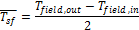
Loop thermal efficiency
The estimated thermal efficiency at design conditions corresponding to the input selections on the Collector and Receiver page. If the Polynomial fit heat loss model is used, the polynomial equation for temperature-based heat loss is evaluated at the average design-point solar field temperature, where that temperature is equal to the average of the outlet and inlet solar field temperatures on the Solar Field page.
If the Evacuated tube heat loss model is used, SAM estimates thermal efficiency based on the user-specified Estimated avg. heat loss and Variant weighting fraction values on the Collector and Receiver page.
Note
The design-point thermal efficiency value is used only to size the solar field aperture area and is not part of the simulation calculations.
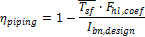
Piping thermal efficiency
The estimated non-collector piping thermal efficiency at design. This value is calculated based on the Piping thermal loss coefficient on the Parasitics page. The estimated efficiency is equal to the compliment of the product of the average solar field operating temperature at design and the heat loss coefficient divided by the design-point solar irradiation.
Total loop conversion efficiency
The total estimated loop conversion efficiency at design, including collector optical performance, receiver thermal losses, and piping thermal losses. This value is used to size the solar field aperture area given a solar multiple and required power cycle thermal input.
Total required aperture, SM=1
The calculated aperture area that provides a thermal output from the solar field that exactly matches the power cycle design-point thermal input (i.e. a solar multiple of 1). This value is used to calculate the corresponding number of loops at a solar multiple of 1.
Required number of loops, SM=1
The number of loops that fulfills the thermal output requirement of the solar field at a solar multiple of 1.
Actual number of loops
The number of loops in the solar field that produces a thermal output at design equal to the power cycle thermal input rating times the solar multiple.
Actual aperture
The actual aperture area is a calculated value equal to the product of the actual number of loops and the reflective aperture area of a single loop, as calculated above.
Actual solar multiple
The actual solar multiple is calculated using the thermal power produced at design with an aperture area equal to the Actual aperture calculated value, the design-point ambient and irradiation conditions, and the thermal power requirement of the power cycle.
The actual solar multiple may differ from the user-specified input value if the sum of the thermal output provided by the integer number of loops matches the product of the solar multiple (user input) and the power cycle thermal requirement.
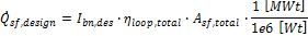
Field thermal output
Thermal energy output from the solar field at design conditions. This value is calculated based on the actual aperture area of the field and the estimated loop conversion efficiency at design.
Solar Field Parameters#
- Number of modules in boiler section
The number of boiler units in series in a single loop, each with geometry as defined on the Collector and Receiver page under the Linear Fresnel Boiler Geometry dropdown option.
- Solar elevation for collector nighttime stow, deg
The solar elevation angle (above the horizon) that sets the operational limit of the collector field in the evening hours. When the solar elevation angle falls below this value, the collector field will cease operation.
- Solar elevation for collector morning deploy, deg
The solar elevation angel (above the horizon) that sets the operational limit of the collector field in the morning hours. When the solar elevation angle rises above this value, the collector field will begin operation.
- Stow wind speed, m/s
The maximum allowable wind velocity before the collectors defocus and enter safety stow position. The solar field cannot produce thermal energy during time steps in which the ambient wind velocity exceeds this limit.
- Collector azimuth angle (degrees)
The azimuth angle of all collectors in the field, where zero degrees is pointing toward the equator, equivalent to a north-south axis. West is 90 degrees, and east is -90 degrees. SAM assumes that the collectors are oriented 90 degrees east of the azimuth angle in the morning and track the daily movement of the sun from east to west.
The collector azimuth angle variable is not active with the Solar position table option on the Collector and Receiver page . The variable is only active with either the two incidence angle options for specifying the solar field.
Design point ambient temperature,****°C
The reference ambient temperature for the solar field, used as a basis for calculating thermal losses from the receivers and piping. Note that this value is not used as a reference for receiver thermal losses if the evacuated tube receiver option is selected on the Collector and Receiver page.
- Tracking Power (W/m2)
The electric power in Watts per area of collector aperture required by the tracking mechanism of each collector in the field during hours of operation.
- Piping thermal loss coefficient (W/K-m2-aper)
Thermal loss per area of collector aperture.
Steam Design Conditions#
- Cold header pressure drop fraction
The fractional pressure drop across the cold header section of the solar field at design. The absolute pressure drop at design is equal to the fractional drop times the rated turbine inlet pressure.
- Boiler pressure drop fraction
The fractional pressure drop across the boiler section of the solar field at design. The absolute pressure drop at design is equal to the fractional drop times the rated turbine inlet pressure.
- Average design point hot header pressure drop fraction
The fractional pressure drop across the hot header section of the solar field at design. The absolute pressure drop at design is equal to the fractional drop times the rated turbine inlet pressure.
- Total solar field pressure drop
The total calculated solar field pressure drop at design.
- Freeze protection temperature, °C
The temperature below which auxiliary fossil backup heat is supplied to the solar field to prevent water from freezing in the equipment. You should set this value such that a reasonable margin exists between activation of the electric heat trace freeze protection equipment and the actual freezing point of water.
- Field pump efficiency
The isentropic efficiency of the feedwater and recirculation pump (if applicable) in the solar field. The total work required to propel the feedwater is divided by this efficiency value to give the electrical parasitic pumping requirement.
Mirror Washing#
SAM reports the water usage of the system in the results based on the mirror washing variables. The annual water usage is the product of the water usage per wash and 365 (days per year) divided by the washing frequency.
- Water usage per wash
The volume of water in liters per square meter of solar field aperture area required for periodic mirror washing.
- Washing frequency
The number of days between washing.
Plant Heat Capacity#
- Thermal inertia per unit of solar field
The amount of energy required to increase the working temperature of the solar field, per unit aperture area of the solar field. The thermal inertia term is used to model the startup and shutdown transient behavior of the solar field. During startup, the thermal energy produced by the solar field is reduced according to the energy that goes into heating the working fluid, receiver components, piping, fittings, and insulation. This input captures all of those aspects of transient startup in the solar field.
Land Area#
The land area inputs determine the total land area in acres that you can use to estimate land-related costs in $/acres on the Installation Costs and Operating Costs pages.
- Solar field area, acres
The actual aperture area converted from square meters to acres:
Solar Field Area (acres) = Actual Aperture (m²) × Row Spacing (m) / Maximum SCA Width (m) × 0.0002471 (acres/m²)
The maximum SCA width is the aperture width of SCA with the widest aperture in the field, as specified in the loop configuration and on the Collectors (SCA) page.
- Non-solar field land area multiplier
Land area required for the system excluding the solar field land area, expressed as a fraction of the solar field aperture area. A value of one would result in a total land area equal to the total aperture area.
- Total land area, acres
Land area required for the entire system including the solar field land area
Total Land Area (acres) = Solar Field Area (acres) × (1 + Non-Solar Field Land Area Multiplier)
The land area appears on the Installation Costs page, where you can specify land costs in dollars per acre.